untung99.homes: Adobe Illustrator Drawing javatpoint
Untung99 menawarkan beragam permainan yang menarik, termasuk slot online, poker, roulette, blackjack, dan taruhan olahraga langsung. Dengan koleksi permainan yang lengkap dan terus diperbarui, pemain memiliki banyak pilihan untuk menjaga kegembiraan mereka. Selain itu, Untung99 juga menyediakan bonus dan promosi menarik yang meningkatkan peluang kemenangan dan memberikan nilai tambah kepada pemain.
Berikut adalah artikel atau berita tentang Harian untung99.homes dengan judul untung99.homes: Adobe Illustrator Drawing javatpoint yang telah tayang di untung99.homes terimakasih telah menyimak. Bila ada masukan atau komplain mengenai artikel berikut silahkan hubungi email kami di koresponden@untung99.homes, Terimakasih.
We can use to draw some artistic logo, frame, and character in Adobe Illustrator with the help of tools and technologies that are available in Adobe Illustrator.
Vector Graphics
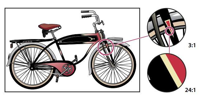
Vectors graphics is the art, which is made up of lines and curves defined by mathematical objects using vectors. According to its geometric characteristics the Vector graphics describes an image. Vector graphics are resolution independent because they maintain crisp edges when resized.
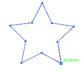
Vector paths
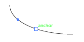
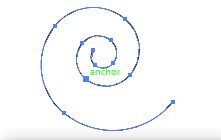
When we draw, we create a line which is called as path. A path can be created using one or more straight/curved line. A point is marked at both the ends called Anchor point that similarly works as the pins holding a thread in place. A path in a vector graphic design can be closed, or open, with distinct endpoints
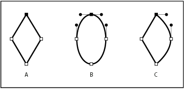
There are two types of anchor point in the path:
Corner point: It is a path that abruptly changes the direction.
Smooth point: At this point, the path segment is connected as a continuous curve.
Points to remember:
Stroke: An outline of a path is called as stroke. A stroke can have a stylized line pattern or have weight, color, and a dash pattern.
Fill: The color gradient that is applied to an open or closed path’s interior area is called as Fill.
Direction Lines and Direction Points
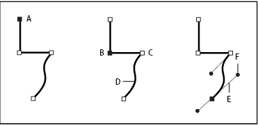
The anchor points of the connecting segments display direction handles when we select an anchor point that connects curved segments, which consist of direction lines that end in direction points. The curved segment’s shape & sized can be determined by this point. If we move the direction point, it reshapes the curves. We cannot see the direction lines inside the final output.
Only the curve in the same side of the point as that direction line is adjusted when you move a direction line on a corner point
When you select an anchor point (left), the direction lines appear on any curved segments, which is connected by the anchor point (right).
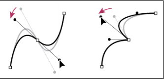
The direction lines, if we are adjusting on a corner point (right) and a smooth point (left)
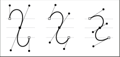
At the anchor points, the direction lines we use are always tangent to the curve. The height of the object can be determined by the length of each direction line. The angle of each direction line determines the depth of the curve, or slope of the curve.
Steps to show or hide direction lines for the selected anchor points
The Direction Selection tool to select the desired anchor points.
Step 1: Go to the control panel below the menu bar.

Step 2: You can select the Hide Handles  for Multiple Selected Anchor Points.
Step 3: Or click on the Show Handles for Multiple Selected Anchor Points.
Step 4: When multiple anchor points are selected, you can also set the preference for to show or hide handles.
Steps to set direction line and direction point display preferences
Step 1: Go to the Edit menu on the menu bar and click on it, a drop-down menu will appear.
Step 2: Now, from the drop-down menu list find and click on the preferences.
Step 3: On the child menu click on the Selection & Anchor display. The Selection & Anchor display dialogue box will appear.
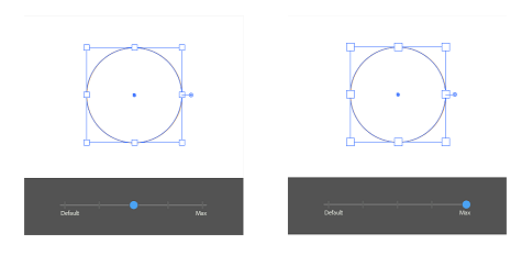
Step 4: Inside the Anchor Point and Handle Display area, you can specify any of the following:
- Size: To change the size of the display, you can adjust the slider. You can also change the anchor points, handles, and bounding boxes.
- You can highlight the anchor point located directly by Mouse Hover
- You can specify the handle end points display.
- Blue solid circle to display direction point

- White circle to display direction points

- Blue solid circle to display direction point
Drawing Modes in Adobe Illustrator
In Adobe Illustrator we can have following three drawing modes:
- The Draw Normal Mode: The icon for the draw normal mode is
 . It is the default drawing mode. You can select the drawing mode below the “Color Selector” tool inside the Tools panel.
- The Draw Behind Mode: The icon for the draw behind mode is
 . If no artwork is selected, it allows us to draw all the artwork behind a selected layer. Or a new object is drawn directly beneath the selected object, if an artwork is selected.
We can use the draw behind mode in the following cases.- If we want to create new layers.
- If we want to place any symbol.
- If we want to place any files from the File menu.
- The Draw Inside Mode: The icon for the draw inside mode is
 . Using this mode, we can draw inside the selected object and eliminates the need of forming multiple tasks. For example – drawing/ altering drawing, selecting, altering stack order, and creating a clipping mask. We can enable the draw inside mode only during a single selected object, i.e. path, compound path, or text.
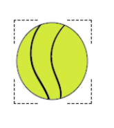
Draw pixel-perfect art in Adobe Illustrator
Using Adobe Illustrator, we can create pixel-perfect that is sharp and crisp looking over screens. It can be created at different stroke width and alignment options.
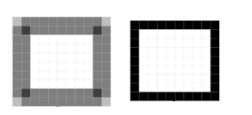
We can save pixel-alignment without distorting the artwork when we transform an object. It works for individual path segments as well as for objects and anchor points that comprises of pixels. We can use this functionality when we want to copy-paste a non-pixel-aligned objects from other documents. We can align the objects with the pixel grid and select object segment/an object in our existing art.
Steps to create an existing object pixel perfect:
Step 1: You can click on the Align Selected Art Pixel Grid icon in the control panel
Step 2: You can choose the object.
Step 3: After that, click on pixel perfect option.
Step 4: Finally, Right-click on the object then choose Make Pixel Perfect from the in-context menu.
Drawing simple lines and shapes in Adobe Illustrator
Draw straight line in Adobe Illustrator
We can use the line segment tool  when we want to draw a straight line. Follow these steps to use the Line Segment Tool:
Step 1: Go to the tool palate and select the Line Segment Tool.
Step 2: Then go to the Artboard or work area where you want the line to begin then click and drag the mouse pointer to where you want the line to end.
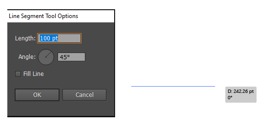
Step 3: You can choose the length and angle of the line you want to draw.
Draw arcs in Illustrator
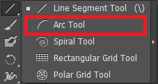
Step 1: Go to the tools palate and click and hold the mouse button for two second over the line segment tool  then select the Arc tool
  from the drop-down menu.
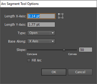
Step 2: Then go to the Artboard or work area where you want the arc to begin then click and drag the mouse pointer to where you want the line to end.
- To specify the width of the arc, modify the X-Axis.
- To specify the height of the arc, modify the Y-Axis.
- You can specify the mode of the path, whether it is a open path or closed path using the Type
- To specify the direction of the arc, use the Base Along
- To specify the direction of the arc slope, use the Slope
- The fill arc option is used to fill the arc with the current fill color.
Draw spirals in Illustrator
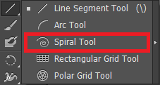
Step 1: Go to the tools palate and click and hold the mouse button for two second over the line segment tool  then select the spiral tool
  from the drop-down menu.
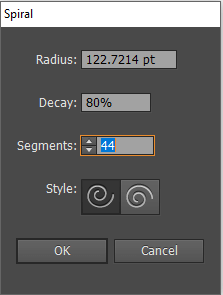
Step 2: Then go to the Artboard or work area where you want the spiral to begin then click and drag the mouse pointer to how big you want to draw a spiral.
- The Radius option will be used specify the distance from the center to the outermost point in the spiral.
- The decay option will be used to specify the amount of wind.
- To specify the number of segments the spiral has, we can use segment.
- We can use style to specify the direction of the spiral.
Draw Grids in Illustrator
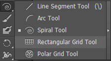
We can quickly draw rectangular and polar grids using the grid tool. To create a rectangular grid, we can use the rectangular grid tool  to create a specified size with the specified number of drivers.
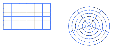
To create a center concentric circles of a specified size and a specified number of dividers, use the Polar Grid tool  .
.
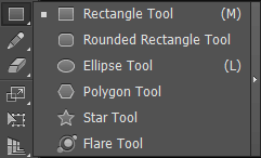
Draw rectangles and squares in the Illustrator.
Step 1: Go to the tools palate and select the Rectangle tool  .
.
Step 2: Now click on the Artboard and Drag diagonally till the desired size of the rectangle/square you draw.

Draw ellipses in Illustrator
Step 1: Go to the tools palate and click and hold the mouse button for two second over the Rectangle tool  then select the Ellipse tool
  from the drop-down menu.
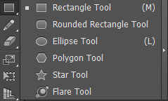
Step 2: Then go to the Artboard or work area where you want the ellipse to begin then click and drag the mouse pointer diagonally till the desired size of the ellipse.
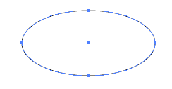
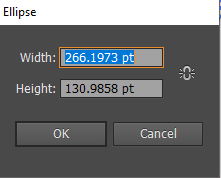
Step 3: Click on the created ellipse to specify it’s width and height.
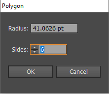
Draw polygons in Illustrator
Step 1: Go to the tools palate and click and hold the mouse button for two second over the Rectangle tool  then select the polygon tool
  from the drop-down menu.
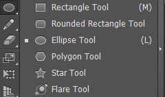
Step 2: Then go to the Artboard or work area where you want the polygon to begin then click and drag the mouse pointer diagonally till the desired size of the polygon.

Step 3: You can specify the radius of the polygon by clicking on the created polygon.
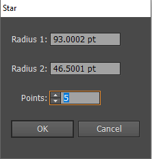
Draw stars in Illustrator
Step 1: Go to the tools palate and click and hold the mouse button for two second over the Rectangle tool  then select the star tool
  from the drop-down menu.

Step 2: Then go to the Artboard or work area where you want the Star to begin then click and drag the mouse pointer diagonally till the desired size of the Star you get.
Step 3: To specify the radius of the star and number of points click on the star.
Draw flares in Illustrator
A flare is a bright centred circle that is created using the flare tool, or a halo, and rays and rings. It is similar to the lens flare that you can see in the photographs due to lens reflection. We can use the handles to position the flare and its ring.
Creating a default flare
Step 1: Go to the tools palate and click and hold the mouse button for two second over the Rectangle tool  then select the flare tool
  from the drop-down menu.
Step 2: Then go to the Artboard or work area where you want the flare to begin then click and drag the mouse pointer to any direction till the desired size of the flare you get. Then click on any anchor point and drag in the desired direction to create a flare.
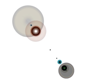
Step 3: Now click on the flare you created to open the Flare tool option dialogue box.
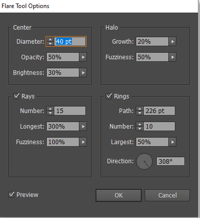
- You can now specify the overall diameter, brightness, and opacity for the center of the flare.
- You can specify the fuzziness of the halo and modify its growth with respect to overall size.
- You can also specify the number of rings and rays for the flare.
Perspective Drawing
In Adobe Illustrator we can draw or render the objects in perspective using its feature that works on established laws of perspective drawing.
Following are the features of Adobe illustrator that are used in perspective drawing;
- Available utilities that are used to define or edit one, two, and three vanishing point perspective in a document.
- We can create objects in the perspective mode directly.
- To control different perspective, we can define parameters interactively.
- The existing objects can be brought in perspective.
- The scale objects can be moved in perspective.
Perspective grid pre-sets
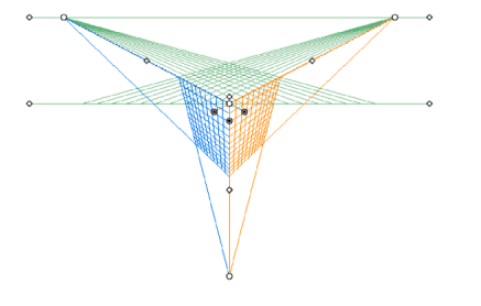
In Adobe Illustrator, we have pre-sets for one-point, two-point, and three-point perspective.
One-point perspective
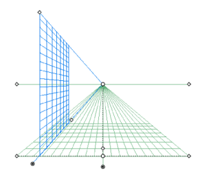
Two-point perspective
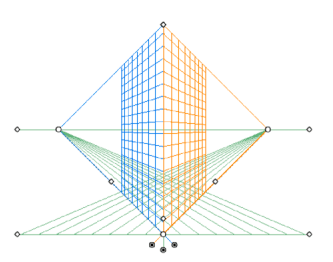
Three-point perspective
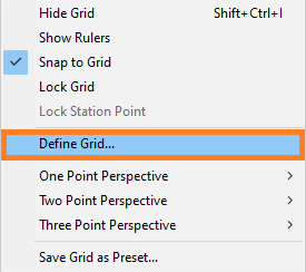
Defining grid presets
Step 1: Go to the menu bar and click on View.

Step 2: Select the perspective grid.

Step 3: Then, click on Define Grid.
A dialogue box will appear where you can configure the following attributes for a pre-set:
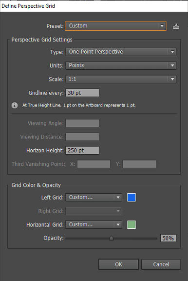
- Name: You can save a new preset by selecting the custom option for the Name drop-down list
- Type: You can select the perspective type using this option.
- Units: You can measure the grid size with the help of unit option in centimetres, inches, pixels, and points.
- Scale: To set the view or artboard and real-world management, you can use the select option.
- Gridline every: It is used to determine the grid cell size.
- Viewing angle: It determines the angle to which the right face of the imaginary cube makes with the picture plane.
- Viewing Distance: You can select the distance between the scene and the observer.
- Horizon Height: It is used to specify the height of the horizon from the ground level.
- Third Vanishing Point: You can enable this when you select the three-point perspective.
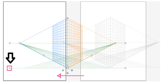
Move the perspective grid in Illustrator
In Illustrator only one grid will be created in a document. We can move the grid over the artboard using the Ground Level weight while the perspective grid tool is selected.
Step 1: Go to the Tools panel and select the Perspective Grid tool  , or press Shift+P.
Step 2: Move your mouse pointer to the ground level point, then drag-and-drop. Your mouse pointer will change to  , when you move your mouse pointer to the ground level point.
Drawing Objects in perspective
We have to use the line group tools or rectangle group tool to draw objects in perspective. We can switch to the perspective selection tool when we use the rectangle or line group tools, by pressing CTRL button.
When we draw an object in perspective, we can use the Smart Guides to align the objects with other object, which is based on the perspective geometry of object. We can specify the height and width value for the object in the same way as we draw earlier in regular mode and use numerical values for any of the line or rectangle group tools.
Drawing with the Pencil tool
The pencil tool works in the same way it works in other Adobe products. It allows us to draw open and closed paths in same way we used to draw with a pencil on paper. The pencil tool is useful while we need fast sketching or creating a hand-drawn look.
The anchor points are not active when we draw using the pencil tool. But we can adjust the anchor point when after we are done with drawing the paths.
Steps to draw a free-form paths using Pencil tool
Step 1: Click over the pencil tool  from Tools palate.
Step 2: Now, position your pointer where you want to draw the path, then drag with a click to draw.
When you drag, A dotted line follows the pointer, and you can see the anchor point appear at both the ends of the path.
Steps to draw closed path using pencil tool
Step 1: Click over the pencil tool  from Tools palate.
Step 2: Now, position your pointer where you want to draw the path, then drag with a click to draw.
Step 3: When you start dragging, hold down the Alt button then a pencil tool displays a small circle that indicates that you are drawing a closed path.
Step 4: When you get the path of your desired size and shape then release the mouse button.
Editing paths
Step 1: Go to the Artboard and select an existing path.
Stem 2: Now, select the pencil tool from the tool palate.
Step 3: Position your cursor on an endpoint of the path.
Step 4: From that anchor point, drag to edit the path.
Connect two paths with the Pencil tool
Step 1: You have to select both the paths by pressing Shift-click or you can drag around the two using the Selection tool.
Step 2: Then, click on the Pencil tool.
Step 3: Now, position your pointer and click from where you want to begin the path, and start dragging toward the other path.
Step 4: Once you started dragging, press Ctrl button. The Pencil tool starts displaying a small merge symbol that indicate you’re adding path to the existing path.
Step 5: Finally, drag until your desired endpoint of the other path, then release the mouse button and Ctrl key.
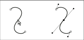
Reshape paths with the Pencil tool
Step 1: Use the selection tool to select the path you want to change.
Step 2: Then, select the Pencil tool and position on or near the path you want to redraw.
Step 3: Now, drag the pointer until you get the path of desired shape.
Pencil tool options
Fidelity: This option is used to control the movement of your mouse or stylus before a new anchor point is added to the drawn path. The higher the value of fidelity, the smoother and less complex the path is. The lower the value resulting in sharper angles, and have more curves that matches the pointer’s movement. The range of fidelity can be 0.5 to 20 pixels.
Smoothness: You can control the amount of smoothing applied to the path using this option. The range of the smoothness can be 0% to 100%. High value represents the smoother the path and the lower value represents more anchor points being created.
Fill New Pencil Strokes: You can use this option to fill the pencil strokes you are drawing, but not to any existing pencil strokes. Before you draw the pencil strokes, don’t forget to select a fill.
Keep Selected: After you draw a path, it determines whether to keep the path selected or not.
Edit Selected Paths: When you are within a certain distance of the drawn path, it determines whether or not you can change or merge it.
Within: _ pixels: To edit the path with the Pencil tools, it determines how close your mouse or stylus must be to an existing path. When the Edit Selected Paths option is selected then only this option is available.